#!html
<h1 style="text-align: left; color: red">
This program is not part of the current lcd4linux. This wiki entry was created for discussion about a program prototype.
<br><br>
</h1>
ctrl_serial
1. Description
This external program is a Controller to interact with the Control plugin.
It writes the state of buttons soldered to a serial port to stdout and switches LEDs depending on bytes read from stdin.
\
2. Preparation
===== 2.1. Wiring
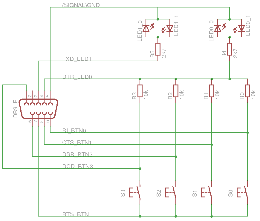
The program requires the following wiring. Two antiparrallel LEDs may be replaced be a 2-Pin-Duo-LED or one of them by a normal diode.
#!html
<h2 style="text-align: left; color: red">
 WITHOUT ANY WARRANTY AND AT YOUR OWN RISK
<br><br>
</h2>
===== 2.2. Download controller
Download and extract the sources.
Create executable with:
gcc -o ctrl_serial ctrl_serial.c util.c -lm
===== 2.3. Set privileges
Set the owner and privileges of the serial port device file (e.g. /dev/ttyS0) with chown and chmod.
Example (with root priviliges):
chown test:test /dev/ttyS0
chmod 600 /dev/ttyS0
3 Test
Run the program in test mode (option -t) to check if it works correctly and which byte value will be sent by the controller on button events. On any button event a new line with the byte to stdout will be shown in different representations.
The state if the LEDs can be modified by typing two number keys followed by the Enter key (see chaper 5.1).
4. Configuration
The structure in the config-file looks like this example which configures a usb mouse controller to navigate within a menu:
Plugin Control {

    active 1

    Controller1 {

        name 'C_serial'

        prog '/home/test/lcd/ctrl/ctrl_serial'
        arg1 '-p'
        arg2 '/dev/ttyS0'

        Key1.action  menu::next()
        Key2.action  menu::prev()
        Key4.action  menu::confirm()
        Key8.action  menu::cancel()
    }

    ...
}
Edit prog path and arg2!
5. Default behavior
===== 5.1. LEDs and stdin
This controller sets the states of the 2 LEDs depending on the bytes it reads from its stdin. Use control::send(...) to send bytes to the controller.
The units of the byte value will set the state of LED0, the tens will set LED1. The hundreds are ignored.
| Digit | LED State |
| 0 | LEDx_0 on, LEDx_1 off |
| 1 | LEDx_0 off, LEDx_1 on |
| 2-8 | switch between LEDx_0 and LEDx_1, 2: very slow - 8: very fast |
| 9 | no state change |
The speed in state 2-8 can be change with the options -2 to -8.
Example (all numbers decimal) if bytes are recieved in the given order:
| Byte | LED1_0 | LED1_1 | LED0_0 | LED0_1 |
| 0 | on | off | on | off |
| 10 | off | on | on | off |
| 92 | no change (off) | no change (on) | blink slow | blink slow |
| 89 | blink fast | blink fast | no change (blink slow) | no change (blink slow) |
===== 5.1. Buttons and stdout
The controller will check which buttona are pressed and write a matching byte pattern to its stdout if one button state has changed, Since only 4 buttons can be soldered to this port the higher 4 bits of this byte are always 0. So the controller might send byte values from 0 to 15 (decimal).
To debounce buttons a button state must be constant for some polling loops to get relevant. This can be modifed with option -b.
6. Options
| Option | Description |
| -h | Help |
| -p <path> | path of serial port (e.g. '/dev/tyyS0'), NOT optional |
| -t | Testmode |
| -d <delay> | Interval between 2 polling loops in milliseconds, default: 10 |
| -b <number> | number of polling loops a button state has to be consant to be regarded. default: 4 |
| -!2-8 <number> | number of loops a LED in blink mode 2-8 keeps in constant state, defaults: -2 100 … -8 5 (geometric sequence) |

